


MOXA ICF-1171I Series
Industrial CAN-to-fiber converters for distance extension
 egenskaber
 beskrivelse
 yderligere information
 lignende produkter
 udskriv denne side
 føj til notater
 vis mine notater
 PDF
PDF
 egenskaber
 beskrivelse
 yderligere information
 PDF
PDF
- Transmits data for up to 40 km over optical fiber
- Converts CAN signals to fiber and vice versa
- Supports CAN 2.0A, CAN 2.0B, and CAN FD; conforms with the ISO 11898 standard
- CAN 2.0 supports auto-baudrate
- CAN 2.0 arbitration rate up to 1 Mbps
- CAN FD arbitration rate up to 1 Mbps; data rate up to 5 Mbps
- Dual power inputs for redundancy
- Wide-temperature model available for -40 to 75°C environments
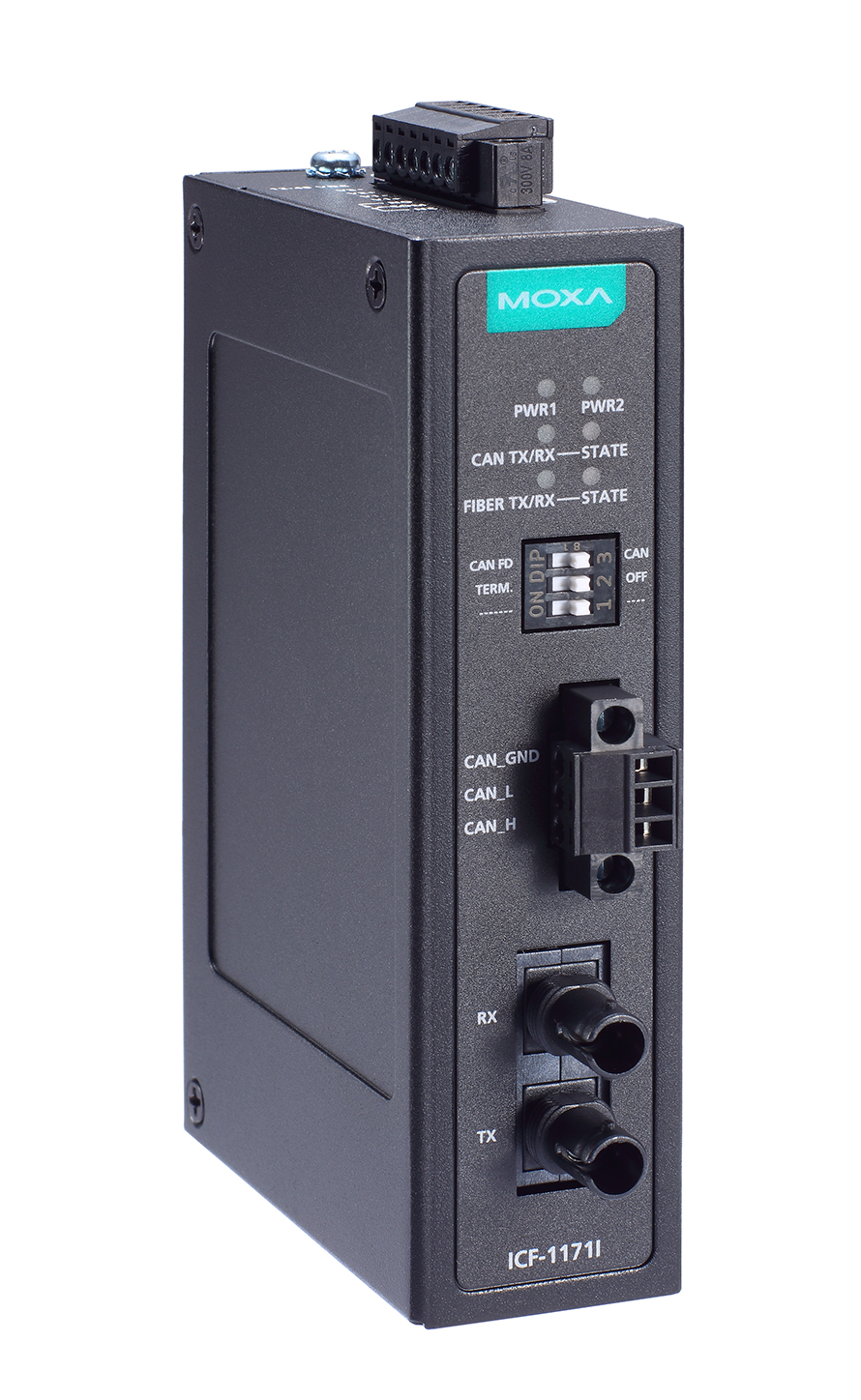
- DIP switch for 120-ohm terminal resistance
- Rotary switches for CAN 2.0/CAN FD arbitration and data rate configuration
- LEDs for CAN bus diagnostics, fiber diagnostics, and power input status
The ICF-1171I Series CAN-to-fiber converters are used in pairs to connect two CAN 2.0 or two CAN FD devices or networks via single-mode or multi-mode optical fiber. The ICF-1171I provides 2-kV isolation protection for the CAN interface and dual power inputs to ensure that your CANbus system will work uninterrupted.
Extend the CAN Bus Transmission Distance
The total transmission distance of a CAN 2.0 or CAN FD system can be extended by 2 km (multi-mode fiber) or by 40 km (single-mode fiber) using ICF-1171I converters, regardless of the CAN baudrate.
Easily Fulfil Various Communication Scenarios
Two CAN 2.0 networks or CAN FD networks can communicate with each other using different baudrates. The ICF-1171I converters can automatically detect the baudrate of the connected CAN 2.0 device and apply the baudrate to itself. Therefore, users do not need to know the baudrate of the connected CAN 2.0 device. This is an extremely convenient feature. Baudrates can also be set to a predefined value via rotary switches.
Easily Troubleshoot Communication Issues
It is easy to check if an issue exists on the CAN bus or the Fiber link. The ICF-1171I converters are provided with LEDs that indicate the fiber link state, fiber communication status, CAN bus state, and CAN bus communication status.
Specifications
| Serial Interface | ||||||||||||||||||||||||||||||||||||||||||
|---|---|---|---|---|---|---|---|---|---|---|---|---|---|---|---|---|---|---|---|---|---|---|---|---|---|---|---|---|---|---|---|---|---|---|---|---|---|---|---|---|---|---|
| Optical Fiber | 100Base-Fx ports (single-mode/multi-mode ST connector)
|
|||||||||||||||||||||||||||||||||||||||||
| CAN Interface | ||||||||||||||||||||||||||||||||||||||||||
| Isolation | 2 kV (built-in) | |||||||||||||||||||||||||||||||||||||||||
| No. of Ports | 1 | |||||||||||||||||||||||||||||||||||||||||
| Signals | CAN_L, CAN_H, CAN Signal GND | |||||||||||||||||||||||||||||||||||||||||
| Terminator | N/A, 120 ohms (by DIP) | |||||||||||||||||||||||||||||||||||||||||
| Protocols | CAN 2.0A, CAN 2.0B, CAN FD, compatible with ISO 11898 standard (DIP switch to select CAN 2.0/CAN FD setting) | |||||||||||||||||||||||||||||||||||||||||
| Fiber Interface | ||||||||||||||||||||||||||||||||||||||||||
| No. of Ports | 1 | |||||||||||||||||||||||||||||||||||||||||
| Connector | ICF-1171I-S-ST/ ICF-1171I-S-ST-T: Single-mode ST connector ICF-1171I-M-ST/ ICF-1171I-M-ST-T: Multi-mode ST connector |
|||||||||||||||||||||||||||||||||||||||||
| Optical Fiber | Single-mode, typical distance 40 km Multi-mode, typical distance 2 km |
|||||||||||||||||||||||||||||||||||||||||
| Power Parameters | ||||||||||||||||||||||||||||||||||||||||||
| Input Current | 188.5 mA (max.) | |||||||||||||||||||||||||||||||||||||||||
| Input Voltage | 12 to 48 VDC | |||||||||||||||||||||||||||||||||||||||||
| No. of Power Inputs | 2 | |||||||||||||||||||||||||||||||||||||||||
| Power Connector | Terminal block | |||||||||||||||||||||||||||||||||||||||||
| Relays | ||||||||||||||||||||||||||||||||||||||||||
| Contact Current Rating | Resistive load: 1 A @ 30 VDC | |||||||||||||||||||||||||||||||||||||||||
| Pinouts | NC, COM, NO | |||||||||||||||||||||||||||||||||||||||||
| Physical Characteristics | ||||||||||||||||||||||||||||||||||||||||||
| Housing | Metal | |||||||||||||||||||||||||||||||||||||||||
| IP Rating | IP30 | |||||||||||||||||||||||||||||||||||||||||
| Dimensions | 30.3 x 70 x 115 mm (1.19 x 2.76 x 4.53 in) | |||||||||||||||||||||||||||||||||||||||||
| Weight | 294 g (0.65 lb) | |||||||||||||||||||||||||||||||||||||||||
| Installation | DIN-rail mounting, Wall mounting (with optional kit) | |||||||||||||||||||||||||||||||||||||||||
| Environmental Limits | ||||||||||||||||||||||||||||||||||||||||||
| Operating Temperature | ICF-1171I-S-ST, ICF-1171I-M-ST: 0 to 60°C (32 to 140°F) ICF-1171I-S-ST-T, ICF-1171I-M-ST-T: -40 to 75°C (-40 to 167°F) |
|||||||||||||||||||||||||||||||||||||||||
| Storage Temperature (package included) | -40 to 85°C (-40 to 185°F) | |||||||||||||||||||||||||||||||||||||||||
| Ambient Relative Humidity | 5 to 95% (non-condensing) | |||||||||||||||||||||||||||||||||||||||||
| Standards and Certifications | ||||||||||||||||||||||||||||||||||||||||||
| EMC | EN 55032/35 | |||||||||||||||||||||||||||||||||||||||||
| EMI | CISPR 32, FCC Part 15B Class A | |||||||||||||||||||||||||||||||||||||||||
| EMS | IEC 61000-4-2 ESD: Contact: 8 kV; Air: 15 kV IEC 61000-4-3 RS: 80 MHz to 1 GHz: 3 V/m IEC 61000-4-4 EFT: Power: 4 kV; Signal: 2 kV IEC 61000-4-5 Surge: Power: 2 kV, Signal: 2 kV IEC 61000-4-6 CS: 150 kHz to 80 MHz: 10 V/m; Signal: 10 V/m IEC 61000-4-8 PFMF |
|||||||||||||||||||||||||||||||||||||||||
| International Approval | KC | |||||||||||||||||||||||||||||||||||||||||
| Safety | UL 62368-1, EN 62368-1 | |||||||||||||||||||||||||||||||||||||||||
| Vibration | IEC 60068-2-6 | |||||||||||||||||||||||||||||||||||||||||
| MTBF | ||||||||||||||||||||||||||||||||||||||||||
| Time | 2,412,885 hrs | |||||||||||||||||||||||||||||||||||||||||
| Standards | Telcordia (Bellcore), GB | |||||||||||||||||||||||||||||||||||||||||
| Warranty | ||||||||||||||||||||||||||||||||||||||||||
| Warranty Period | 5 years | |||||||||||||||||||||||||||||||||||||||||
Ordering Information
| Model Name | Operating Temp. | Fiber Module Type |
|---|---|---|
| ICF-1171I-S-ST | 0 to 60°C | Single-mode ST |
| ICF-1171I-S-ST-T | -40 to 75°C2 | Single-mode ST |
| ICF-1171I-M-ST | 0 to 60°C | Multi-mode ST |
| ICF-1171I-M-ST-T | -40 to 75°C | Multi-mode ST |
Accessories (sold separately)
- Mounting Kits
- WK-30-02
Wall-mounting kit, 2 plates, 4 screws, 30 x 66.8 x 2 mm
 Kunder, der kiggede på dette produkt, kiggede også på